2.3. Setup the Switch
2.3.1. Setup Network Settings
The next step is to check and setup network settings:
(Routing) #show network
IP Address..................................... 0.0.0.0
Subnet Mask.................................... 0.0.0.0
Default Gateway................................ 0.0.0.0
Burned In MAC Address.......................... 60:EB:69:A9:22:05
Locally Administered MAC Address............... 00:00:00:00:00:00
MAC Address Type............................... Burned In
Network Configuration Protocol Current......... None
Management VLAN ID............................. 1

(Routing) #
All ports are turned off, so no DHCP assignment received yet. To turn on all ports:
(Routing) #configure

(Routing) (Config)#no shutdown all

(Routing) (Config)#exit

(Routing) #show port all
               Admin   Physical   Physical   Link   Link    LACP   Actor
 Intf   Type    Mode    Mode       Status   Status  Trap    Mode   Timeout
------ ------ ------- ---------- ---------- ------ ------- ------ --------
0/1           Enable   Auto       1000 Full  Up     Enable Enable long
0/2           Enable   Auto       100 Full   Up     Enable Enable long
0/3           Enable   Auto                  Down   Enable Enable long
0/4           Enable   Auto                  Down   Enable Enable long
0/5           Enable   Auto                  Down   Enable Enable long
0/6           Enable   Auto                  Down   Enable Enable long
0/7           Enable   Auto                  Down   Enable Enable long
0/8           Enable   Auto                  Down   Enable Enable long
0/9           Enable   Auto                  Down   Enable Enable long
0/10          Enable   Auto                  Down   Enable Enable long
0/11          Enable   Auto                  Down   Enable Enable long
0/12          Enable   Auto                  Down   Enable Enable long
0/13          Enable   Auto                  Down   Enable Enable long
0/14          Enable   Auto                  Down   Enable Enable long
0/15          Enable   Auto                  Down   Enable Enable long
0/16          Enable   Auto                  Down   Enable Enable long
0/17          Enable   Auto                  Down   Enable Enable long
0/18          Enable   Auto                  Down   Enable Enable long

--More-- or (q)uit
The next step is to setup the switch IP address:
(Routing) #network parms 192.168.50.91 255.255.255.0 192.168.50.1
Check the network settings:
(Routing) #show network
IP Address..................................... 192.168.50.91
Subnet Mask.................................... 255.255.255.0
Default Gateway................................ 192.168.50.91
Burned In MAC Address.......................... 60:EB:69:A9:22:05
Locally Administered MAC Address............... 00:00:00:00:00:00
MAC Address Type............................... Burned In
Network Configuration Protocol Current......... None
Management VLAN ID............................. 1

(Routing) #
2.3.2. Enabling SSH Access
To enable the SSH access:
(Routing) >enable
Passsword:

(Routing) #ip ssh server enable
2.3.3. Enabling WEB Inteface
To enable the Web interface:
(Routing) >enable
Passsword:

(Routing) #ip http server
2.3.4. Saving Configuration Changes
Warning
Write down the changes to router NVRAM. Otherwise all changes will be lost upon switch reset! This operation may take a few minutes. Management interfaces will not be available during this time.
(Routing) #write memory
Are you sure you want to save? (y/n) y

Config file 'startup-config' created successfully .

Configuration Saved!

(Routing) #
2.4. Configuring Port Mirroring
2.4.1. What is Port Mirroring?
The port mirroring feature allows the switch to copy the network traffic from one or several source port to a destination port. The destination port can mirror packets transmitted or received by the source port(-s) or both. Only one port can be set as a destination port for the mirroring, but the source port can be one or more.
2.4.2. Configuring Port Mirroring via CLI
Setting up a Port Mirroring Session
The following commands enable port mirroring session and configure source and destination ports.
(Routing) #Config
(Routing) (Config) #monitor session 1 mode
(Routing) (Config) #monitor session 1 source interface 0/45 ?
<cr>                     Press Enter to execute the command.
rx                       Monitor ingress packets only.
tx                       Monitor egress packets only.
(Routing) (Config) #monitor session 1 source interface 0/45
(Routing) (Config) #monitor session 1 destination interface 0/46
(Routing) (Config) #exit
Show the Port Mirroring Session
To show the port mirroring session:
(Routing) #show monitor session 1
Session ID   Admin Mode   Probe Port   Mirrored Port   Type
----------   ----------   ----------   -------------   -----
1            Enable       0/46          0/45             Rx,Tx


Monitor session ID “1” - “1” is a hardware limitation.
Show the Status of All Ports
To show the port mirroring session:
(Routing) #show port all
               Admin   Physical   Physical   Link   Link    LACP   Actor
 Intf   Type    Mode    Mode       Status   Status  Trap    Mode   Timeout
------ ------ ------- ---------- ---------- ------ ------- ------ --------
0/1           Enable   Auto       1000 Full  Up     Enable Enable long
0/2           Enable   Auto       100 Full   Up     Enable Enable long
0/3           Enable   Auto                  Down   Enable Enable long

 --More-- or (q)uit

0/40          Enable   Auto                  Down   Enable Enable long
0/41          Enable   Auto                  Down   Enable Enable long
0/42          Enable   Auto                  Down   Enable Enable long
0/43          Enable   Auto                  Down   Enable Enable long
0/44          Enable   Auto                  Down   Enable Enable long
0/45  Mirror  Enable   Auto       100 Full   Up     Enable Enable long
0/46  Probe   Enable   Auto       1000 Full  Up     Enable Enable long
0/47          Enable   Auto                  Down   Enable Enable long
0/48          Enable   Auto                  Down   Enable Enable long
Show the Status of the Source and Destination Ports
Use this command for a specific port. The output shows whether the port is the mirror or the probe port, what is enabled or disabled on the port, etc.
(Ethernet Fabric) #show port 0/45
                 Admin    Physical  Physical  Link     Link     LACP
Intf   Type      Mode     Mode      Status    Status   Trap     Mode
----   ----      ------   --------  --------  ------   ----     ----
0/45   Mirror    Enable   Auto      100 Full   Up      Enable   Enable
(Ethernet Fabric) #show port 0/46
                 Admin    Physical  Physical  Link     Link     LACP
Intf   Type      Mode     Mode      Status    Status   Trap     Mode
----   ----      ------   --------  --------  ------   ----     ----
0/46   Probe     Enable   Auto      1000 Full  Up      Enable   Enable
2.4.3. Configuring Port Mirroring via Web Interface
Note
Web interface needs to be enabled - please see the section 2.3.3. Enabling WEB Inteface
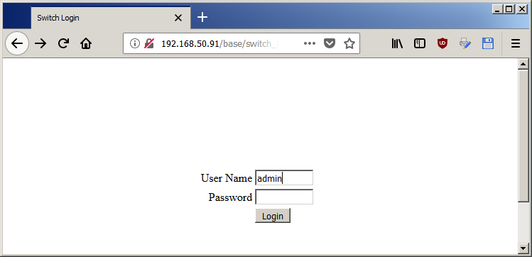
1. Open the logon page in your browser using the switch IP address (according to the network settings you made - see section 2.3.1. Setup Network Settings). In this case the address is 192.168.50.91.
For the user name type admin and fot the password - leave blank:
- After entering the Web interface, expand the System tree of the Navigation field to the
System/Port/Multiple port mirroring.
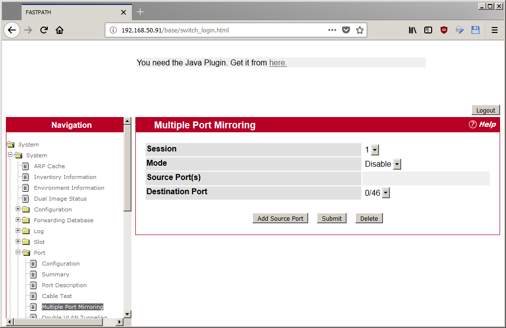
- Setting a Multiple port mirroring is done by pressing a button
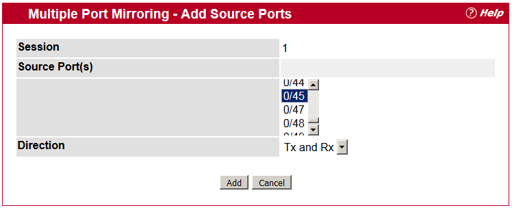
Add source portand entering the following settings:
Source port = 0/45for this case;Direction = Tx and Rx
The entered settings will be confirmed by clicking on the button Add.
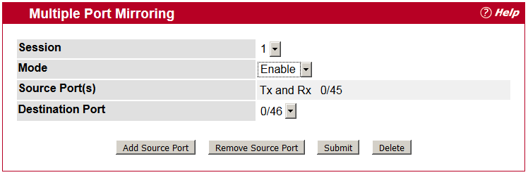
- The final step is to enable the port mirroring by setting the
Mode = Enable, set theDestination port = 0/4(according to this example) and confirmt by pressing theSubmutbutton.